


Seeking for info Diode M1220- Electrical B737NG

Thread Starter
Join Date: Sep 2012
Location: In the sky
Age: 39
Posts: 31
Likes: 0
Received 0 Likes
on
0 Posts
Seeking for info Diode M1220- Electrical B737NG
Hello guys,
I was wondering what is the purpose of the Diode « M1220 » located after the TR3 ?
Is this Diode kind of fail safe to detect with TR has failed?
I was wondering what is the purpose of the Diode « M1220 » located after the TR3 ?
Is this Diode kind of fail safe to detect with TR has failed?

I don't have access to the B737NG electrical diagram, but I am assuming this is a diode between the output of a Transformer/rectifier and the DC busbar it feeds? If so, this is to prevent DC current flowing back into a faulty or switched-off TR.
In simple terms a diode is an electrical 'one way valve' that stops current flow in the reverse direction, and allows current flow in the correct direction. Used in the context above, it forms an automatic switch that switches on and allows current flow if the TR is producing the correct output voltage. If the TR is producing low, or no output voltage, the diode automatically switches off.
If a TR had failed with a shorted output stage for example, with no diode on the output, it could render the busbar U/S by effectively shorting that out too. In shorting out the busbar, the TR and the associated wiring could overheat and/or cause a fire. (This is assuming the busbar has another source of power, not just the TR).
If my assumptions are correct, I hope this helps.

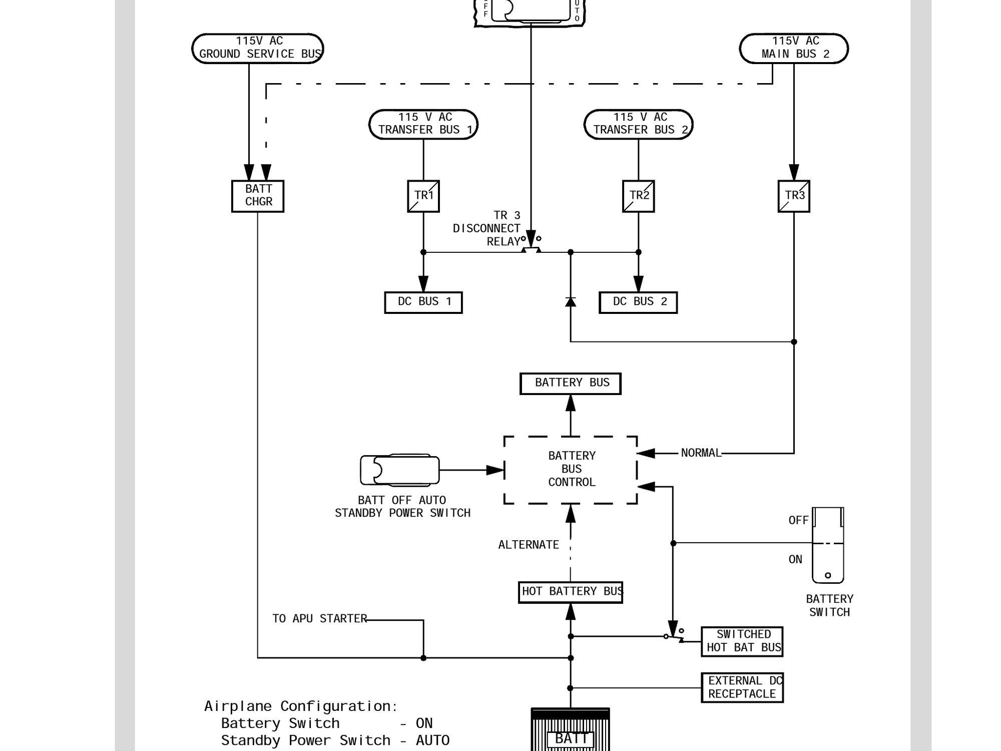
As best I can tell, this diode allows TR3 to power DC BUS 2 if TR2 fails. Additionally, it allows TR3 to power DC BUS 1 if TR1 fails, but only when the DC cross bus tie relay (R9 controlled by SPCU) is closed, which is most of the time. It normally only opens at AFDS G/S capture (also opens if bus transfer switch is not in AUTO or either or both AC transfer busses not powered).
Yes. This is the only diagram I have access to now, and is the B737 Classic. It is probably similar to the NG.
TR3 can feed DC bus 2 (and 1), via the diode, but without the diode, DC bus 2 could permanently feed into the battery bus controller. I don't have the battery bus control detail, but a fault in that could compromise DC bus 2, so the diode prevents a faulty battery bus or controller dragging DC bus 2 down with it.
For any who don't know, a diode switches on if the voltage on the side of the arrow head is higher than the voltage on the side with the bar. i.e. current flows in the direction of the arrow head only. If the voltage on the side of the arrow head is lower than that on the bar side, the diode switches off and does not allow any current flow.
If for example something went badly wrong with the battery or the battery wiring, then without the diode, DC bus 2 could feed loads of current into the battery, or wiring which could cause overheating and fires etc.
Another solution would have been to use switch contactors to route the DC around, but that would be more expense and complexity - it appears that Boeing have kept the system as simple as possible.
From Boeing B737 300/400 FCOM:
Last edited by Uplinker; 10th Apr 2021 at 14:47.
I agree the diode is probably there to isolate one part of the DC system from another, but in the example you mention i.e. a problem with the battery (short circuit etc) the battery bus wouldn’t immediately be affected (unless there were larger problems) as, assuming standby power switch is in auto and you have AC power, the battery bus is powered by TR3 and isolated from the battery via the open battery bus alternate relay. Any problem with the battery would probably manifest itself with popped hot battery bus, battery charger and maybe inverter remote and SPCU CBs (and maybe bat discharge master caution). If you didn’t have AC power then battery bus normal relay (connecting TR3 to battery bus) would be open, battery bus alternate relay would be closed and battery bus would get power directly from the battery. You could, however, get other switching issues affecting the battery bus if you lose the SPCU (which is on the battery side of the DC SYSTEM) as you lose some control of these relays I believe.
